
SCRUBBERIST SRH
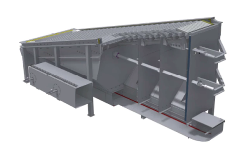
Push grate type SRH is designed for combustion of biofuels with high ash content.
The push grate is specially designed for open bottom boilers.
Depending on the grate size, the push grate can be supplied with 1 or 2 grate trolleys.
Secondary air system, recirculation air system and hydraulic station are ordered separately depending on the fuel bed and water content.
The push grate is equipped with a bricked-in firebox, which ensures that the combustion chamber temperature is kept at an optimal level for combustion.
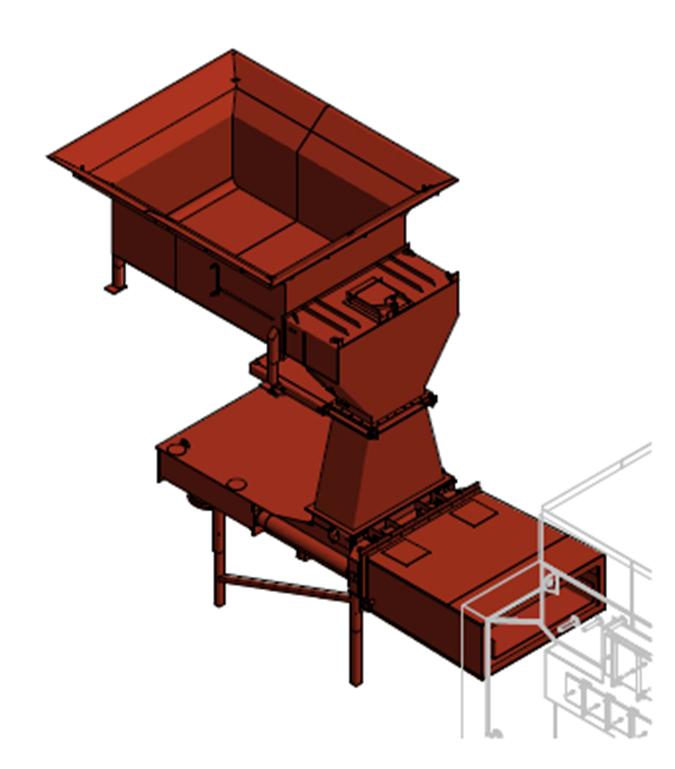
Complete wood chip framing system
Single hopper for receiving wood chips, with hydraulic discharge at the bottom, for dosing hopper. Also available as a double funnel.
Hydraulically operated fire damper equipped with an accumulator, which ensures that the damper also shuts off in the event of a power failure.
The dosing tank is equipped with an infrared level control and an automatic sprinkler system that is activated if the temperature in the dosing tank becomes too high, e.g. due to fire.
Hydraulically driven pusher, which pushes the material from the dosing hopper through the water-cooled channel into the boiler box. The pusher runs in step or frequency controlled mode, the size of which depends on the boiler load, ensuring a completely even feeding of the fuel.
Water-cooled duct to ensure a “chip plug” between the pusher and the combustion grate, thus preventing false air intake. The water-cooled duct ensures that the system can withstand a backfire without risk of breakdown. At the transition from the water-cooled duct to the pusher, a number of fire nozzles are placed to further protect against backfire. The duct is built and secured according to the pressure/temperature of the boiler and is connected directly to the boiler circuit.
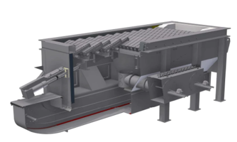
CHIP-BARK PUSHER
The piston of the pusher is driven by double-acting hydraulic cylinders.
The pusher pushes the material from the dosing hopper through the water-cooled/cast channel to the combustion grate.
When the fuel has been pushed in at full piston stroke, the piston moves back to the starting position and a new portion of fuel can be introduced.
The cycle is repeated continuously as operation of the pusher. This runs in a run/pause step, the size of which is dependent on the boiler load.
The speed is set automatically from the control panel and is temperature dependent on the boiler flow temperature. The position of the piston rod is controlled by sensors. The temperature in the outlet of the pusher is monitored by thermostat, both electrical and mechanical.
The pusher is equipped with a system that prevents backfire by controlling the temperature of the feed system.
Automatic sprinkler system is activated if the temperature in the dosing tank becomes too high (above 95oC). A BVTS valve will open to extinguish the fire. The valve will close when the temperature in the dosing system is low again and operation can be resumed.
The system runs automatically. However, it may be necessary to clean the dosing system after a fire.
The chip pusher is used for feeding solid fuels such as bark, shavings, wood chips into combustion grates:
- Wet bark, wood chips and shavings – moisture content 35% – 65%, grain size up to 10x20x350 mm.
- The pusher is available in several sizes.
- Legs for the pusher are available with adjustable feet.
PUSHING GRATE SR-MC
Push grate type SR-MC is designed for combustion of biofuels with high ash content.
The push grate is specially designed for open bottom boilers.
Depending on the grate size, the push grate can be supplied with 1 or 2 grate trolleys.
Secondary air system, recirculation air system and hydraulic station are ordered separately depending on the fuel bed and water content.
The push grate is equipped with a bricked-in firebox, which ensures that the combustion chamber temperature is kept at an optimal level for combustion.
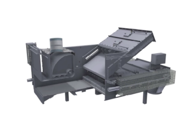
STRAW PUSHER
Straw minnows:
Hydraulically driven pusher, which pushes the material from the dosing hopper through the water-cooled channel into the boiler box. A mixer mounted on the pusher ensures that the material is evenly spread. The pusher runs at a variable speed depending on the boiler load, which ensures even feeding of the fuel.
The water-cooled duct should ensure a “straw plug” between the pusher and the combustion grate, thus preventing false air intake. The pusher piston is equipped with emptying pistons, which are used at STOP of the plant, to ensure that the pusher is emptied of material and backfire is prevented.
The straw pusher is driven by a hydraulic unit which also operates fire dampers. The unit is equipped with an accumulator, so the fire damper can close in the event of a power failure.
Fire dampers:
The fire damper is installed between the pusher and the water-cooled duct for shut-off between the combustion on the grate and the pusher system. The function of the fire damper is to close in case of alarms or shutdown of the system, which could cause fire to migrate from the boiler to the pusher. The fire damper closes by means of two hydraulic cylinders pulling a heavy steel plate between the pusher and the water-cooled duct (1).
Water cooling and fire dampers:
The fire damper is equipped with water cooling which is activated by alarms after a set time when the fire damper must close for safety reasons. The water cooler is mounted down into the extension piece (3) and will spray water in via nozzles. Note: When working in the pusher or the water-cooled duct, red safety bolts must be fitted (2), as the fire damper hydraulics are equipped with accumulator and therefore have pressure on the cylinder of the fire damper. Furthermore, the pressure from accumulator to tank must be equalized by opening the valve from accumulator to tank at the hydraulic station.